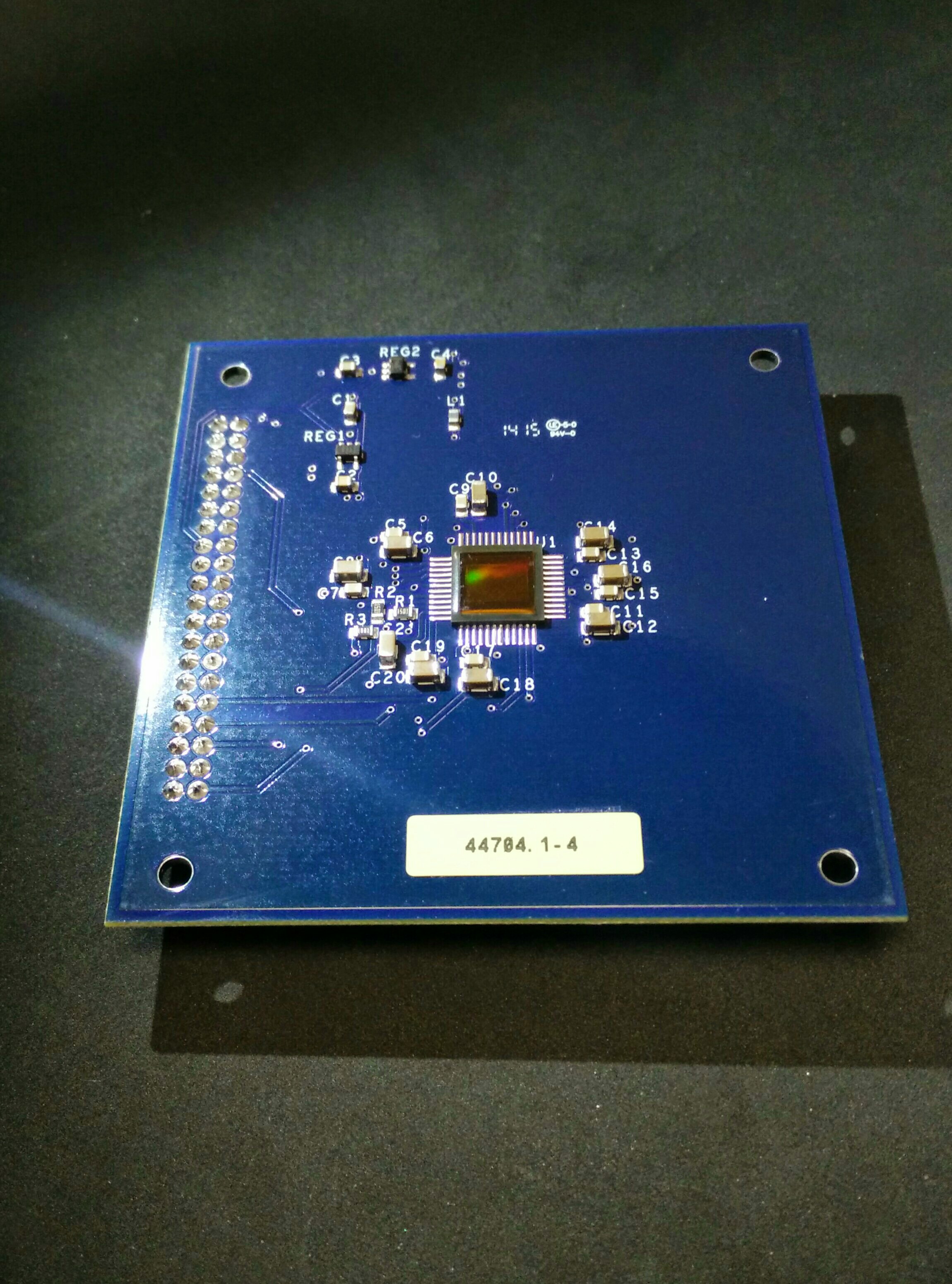
This Printed Circuit Board contains the Image Sensor that is the overall input to our system. This Image Sensor detects light values on an individual pixel by pixel basis, and then outputs these pixel values through the header to the other board.
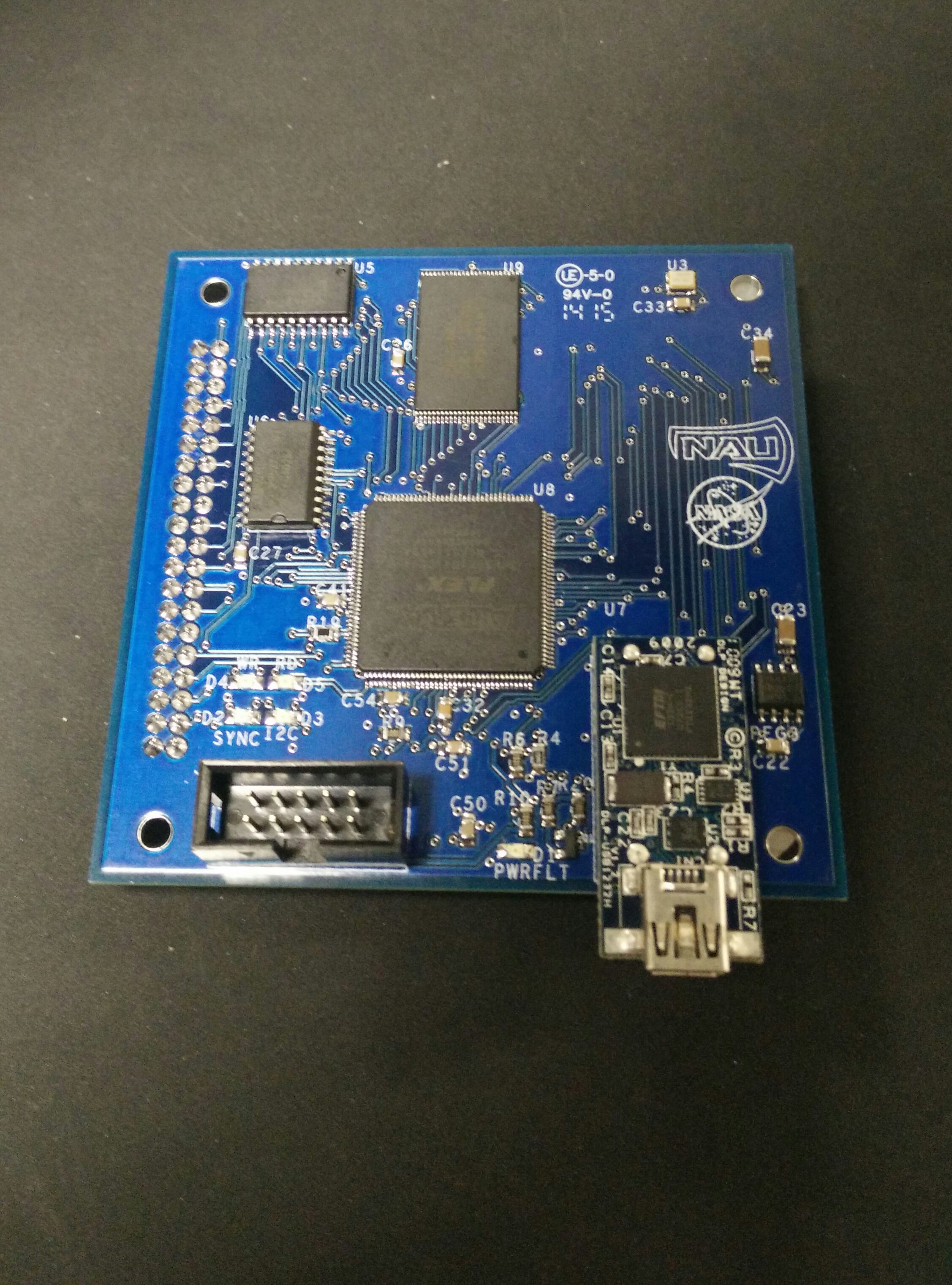
This Printed Circuit Board contains all of the components that control the overall functionality of this design. The data from the Image Sensor is passed through the ribbon cable onto this board, where it is stored into memory (RAM) banks. Once the full image has been stored, the Field Programmable Gate Array (FPGA), which controls all of the data flow operations, then closes the Tri-State buffer, which stops allowing the Image Sensor to pass data onto this control board. The FPGA then opens data flow from the RAM bank to the USB adapter, which passes the data out to the computer, which is running MATLAB. This basic data flow process continues for every image that is taken.
Additionally, there is a JTAG header on this board, which is used to load the Control Unit code onto the board. This code is stored into the EPROM, which provides the control code to the FPGA upon start up of the device.