Schedule
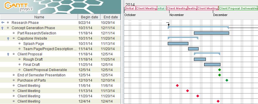
During the Concept Generation phase NASA Team 1 discovered which design decision would work the best for the overall product. Mr. Holland, the client for this project, was especially useful during this phase by supplying NASA team 1 with materials and guidance essential to the project. The team used several resources during this time, mainly part vendors such as Digikey, Mouser, and Arrow. The bulk of this phase of the design was dominated with parts research, however, during the last section of this phase the team also looked at the state machines provided them by Mr. Holland, in order to adapt his design for new componentry. This portion of the concept generation phase was essential as it helped NASA team 1 to formulate their design ideas in a meaningful way i.e. in a series of state diagrams which could then be adapted to the AHDL code used in the design. This portion of the design was essential to furthering this team's understanding of this complex and interesting project.
There has been no testing up to this point, all testing will completed in the detailed design phase.
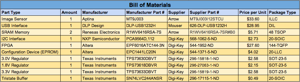
A design decision had to be made concerning what voltages the final system would operate on. This decision affected part selection because many parts are available in only one voltage range. The final voltage ranges selected were 3.3 V for the control board which contains the FPGA, RAM, and USB adapter. Other voltages of 3.0 V and 1.8 V were used for the sensor board which contain the image sensor.
A design decision had to be made concerning the selection of the size and brand of memory units. This decision was narrowed down to two parts. The first was a brand that our client was familiar with but could only be found in a smaller size that would require three banks of RAM. The other part, which was chosen in the end, was a less common brand. However, it was large enough to eliminate one of three RAM banks.
The final design decision was a general decision on whether to select more expensive and higher quality parts which fell out of budget constraint. These parts included radiation hardened SRAM, higher function FPGA, and tantulum or ceramic capacitors.