Design 1
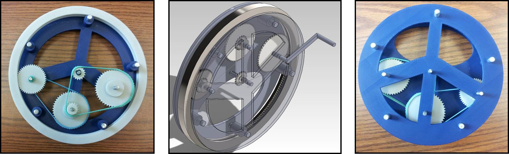
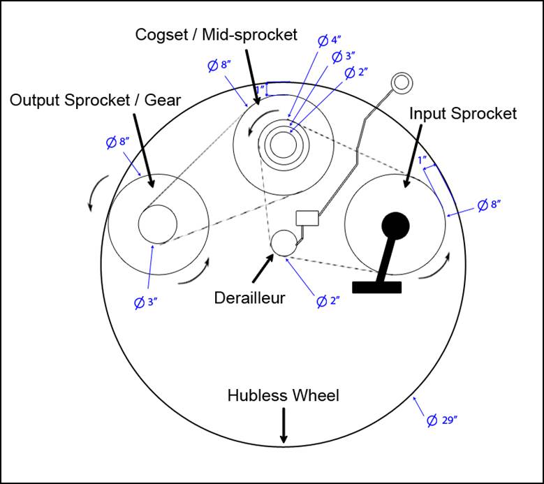
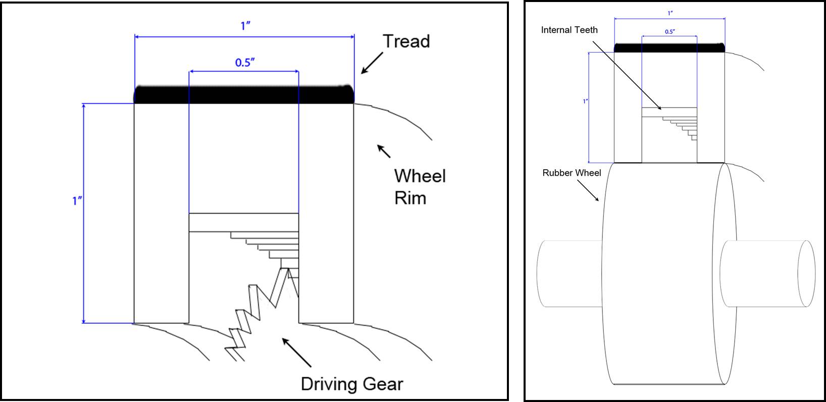
This design integrates a typical bicycle derailleur system within the circumference of the rim and generates rotational motion to a internally-geared hubless wheel. The wheel is supported by multiple free-spinning rubber wheel connected with the frame. Motion begins at the input sprocket shown on the right side of Figure 1. This sprocket is connected on the same axle as the pedaling mechanism where the user will input rotational motion. This motion is then transferred via chain into the derailleur system. Depending on the user-selected setting on the derailleur dial, the chain will link to either a 2", 3", or 4" diameter sprocket in a group called a cluster. These efficiencies are detailed in Table 1. On the same axle as the cluster component is another, larger sprocket. This sprocket then transfers rotational motion via a second chain to a smaller sprocket in the front of the wheel (left side of Figure 1). This sprocket is coaxial with an 8" diameter gear, which locks into the internal gearing of the hubless wheel and generates forward motion. A more detailed view of the wheel connection is shown in Figure 2. The rim of the hubless wheel has a 0.5" groove in the center where the internal teeth are located. This allows for the driving gear to make contact with the teeth while the rubber wheel contacts the smooth surface of the rim.
|
|
This design presents riders with a more compact and safe transmission option while still maintaining a relatively familiar derailleur assembly.
Design 2
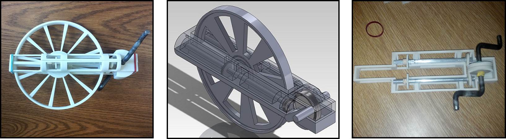
This design redefines bicycle transmissions by removing all chains using only gears and shafts to transfer rotational motion from the pedals to the wheel (See Figures 3 and 4). First, the rider inputs power through the pedals which is then transmitted to the drive shafts through the driving bevel gears. The shafts then rotate the driven gears and propels the wheel forward through multiple rows of "teeth rings" located on the solid hub. This design also consists of a shifting mechanism. When the driver wishes to shift gears, the driven gear will slide along the shaft to a different teeth ring which results in a change in speed and torque. These efficiencies are detailed in Table 2. Row 4 has a larger number of teeth and transmits a slower speed, while row 1 transmits a higher speed. Row 4 will be used for climbing hills, rows 2 and 3 will be used for flat terrain, and row 1 will be used for riding down hills.
|
|
Fabrication Results
Both designs were modeled and assembled using SolidWorks 3D CAD software. In addition to the basic transmission components, unique frames were developed for each design to house the moving parts. Each assembly facilitates realistic rotating components that validate the expected input-output efficiencies. The more basic parts of the assemblies (blue) were printed at NAU, while the pieces with more finite dimensions (gray) were printed at PADT in Phoenix. Various metal dowels were machined and implemented as axels in each assembly.
3D models and prototypes for the hubless and full-wheel designs are shown in Figure 5 and Figure 6, respectively.