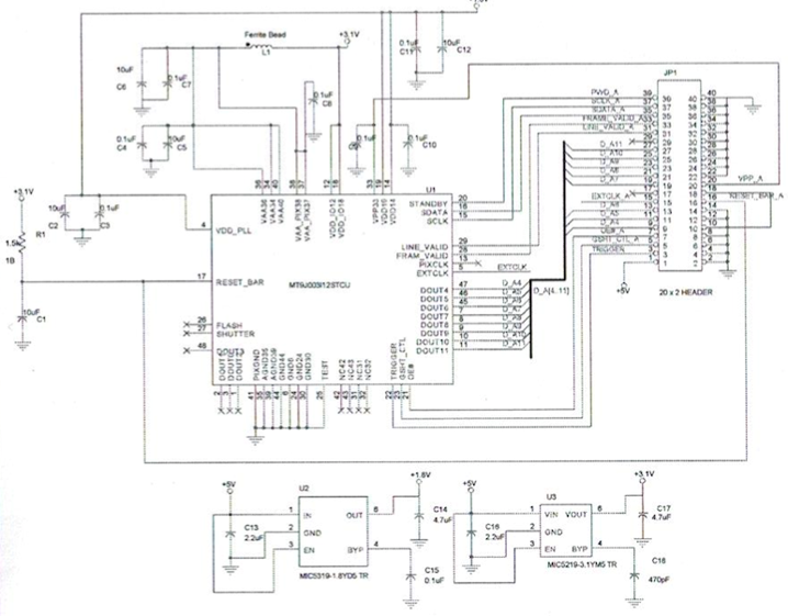
The above Image is of a completed design for the control board this is one of the two designs we created through OrCad. After the designs were complete we moved to board layout for actual wire tracing and component placement of the phyiscal board.
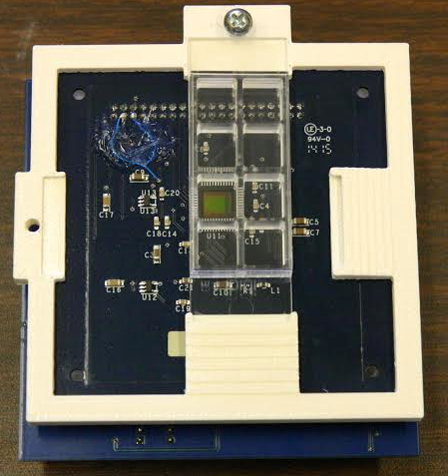
The above image is of the sensor board that the last years team designed. Our team recieved this board to help with the design of the new board. Unfortunatly we were unable to have the time to have our board design fabricated and built in time so that we could test it with the new software. The good news is that we finished the layouts and had it sent to NASA so they could perform testing.
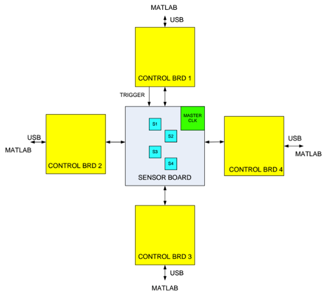
In the end we designed what this block diagram depicts; one sensor board with sensors placed in a Zig Zag pattern and four control boards that control the sensors. The tricky part that we solved in this project was the software aspect and getting four seperate instances of MATLAB to run at the same time and as simply for the user as possible. Our solution was to create a Java program that could act as a controler or director for the MATLAB instances. We designed Java to be a simple jar file, that can be double clicked after some slight file modifications baised on the computer, and it would run four instances of MATLAB for each control board.