Project
Overview:
 Overview: Overview:
Synthetic Aperture Radar (SAR) is a modern radar imaging technique that relies on sophisticated post-processing of high-volume radar data to produce the effect of a very narrow, finely focused beam. A key constraint is that SAR can be used only from moving platforms aimed at relatively stationary targets. Lockheed-Martin is involved in a wide variety of SAR-related business areas, and often needs to test SAR systems or SAR data management systems. Clearly, it would be desirable to do this in the lab rather than on actual aircraft. Thus, we need to simulate the motion of the aircraft and, in particular, the data stream from the aircraft inertial guidance system, in order to test our SAR systems.
Problem:
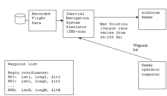
One of the inputs necessary for an airborne Synthetic Aperture Radar (SAR) to operate is platform (i.e. aircraft) navigation information. This information typically comes from the aircraft’s inertial navigation system (INS) which outputs the motion state of the platform at a defined time interval – example 10 ms (100 Hz). The motion state information needed for the SAR to operate is the real-time: Position (latitude, longitude, altitude), Velocity, and Heading of the aircraft. To test a SAR in a static lab configuration, a simulated navigation input is needed. This simulated INS information “tricks” the SAR into thinking it is flying on an aircraft.
Solution:
The task is to build a low cost INS navigation simulator using software running on generic computer hardware such as a Unix based laptop. The navigation simulator requires the following inputs: a minimum of 2 Waypoints in the flight profile and the desired flight speed. A waypoint is a position composed of a latitude, longitude and altitude. The simulator would compute and output a discrete motion state for each position along the flight path connecting the two waypoints. The outputted positions should represent the locations of the aircraft at the specified time interval; therefore, the simulator will need as an input the desired flight speed as an input as well. The user interface (UI) should allow modification to system configurable parameters. The UI should be written in the JAVA programming language for portability (Swing). The simulator will also need a status interface that provides feedback about the motion state as the plane flies from waypoint to waypoint. This information will be very similar to the status information that is provided by a typical hand held GPS unit. In addition, visual feedback (GUI), such as an aircraft icon moving between the waypoints, is expected.
A truly sophisticated simulator would have the ability to fly around a spherical earth. For the sake of SAR checkout in a lab, the simulator can assume that the earth is flat and that the waypoints are relatively close – less than 200 Km between waypoints.
The output of the simulator is a data file that contains time tagged motion states for each sample interval between the waypoints. Each motion state record will contain the position, velocity, and aircraft heading. |
Knowledge, skills, and expertise that will be required
for this project: |
- Java/Swing – The user interface will be developed using this. Version 5.0 minimum.
- Java networking --- some knowledge of Java sockets may be required.
- Some basic knowledge of vector mathematics – required for navigation computations.
- Some working knowledge of linear algebra is recommended.
- Working knowledge of concurrent programming (multi-threaded).
|