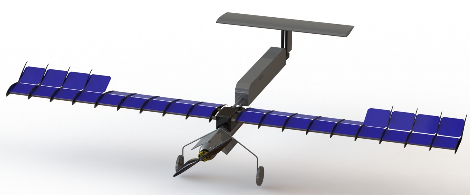
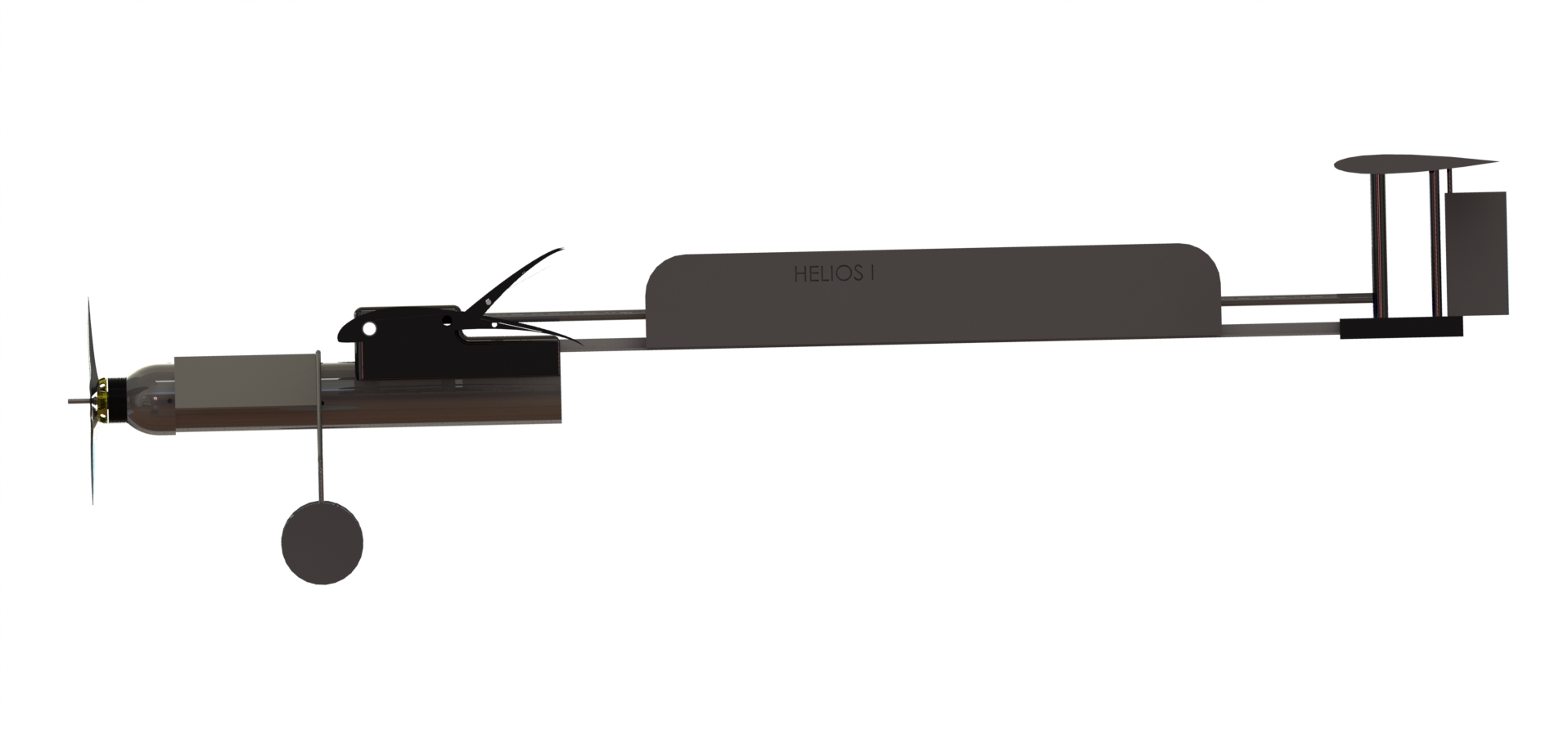
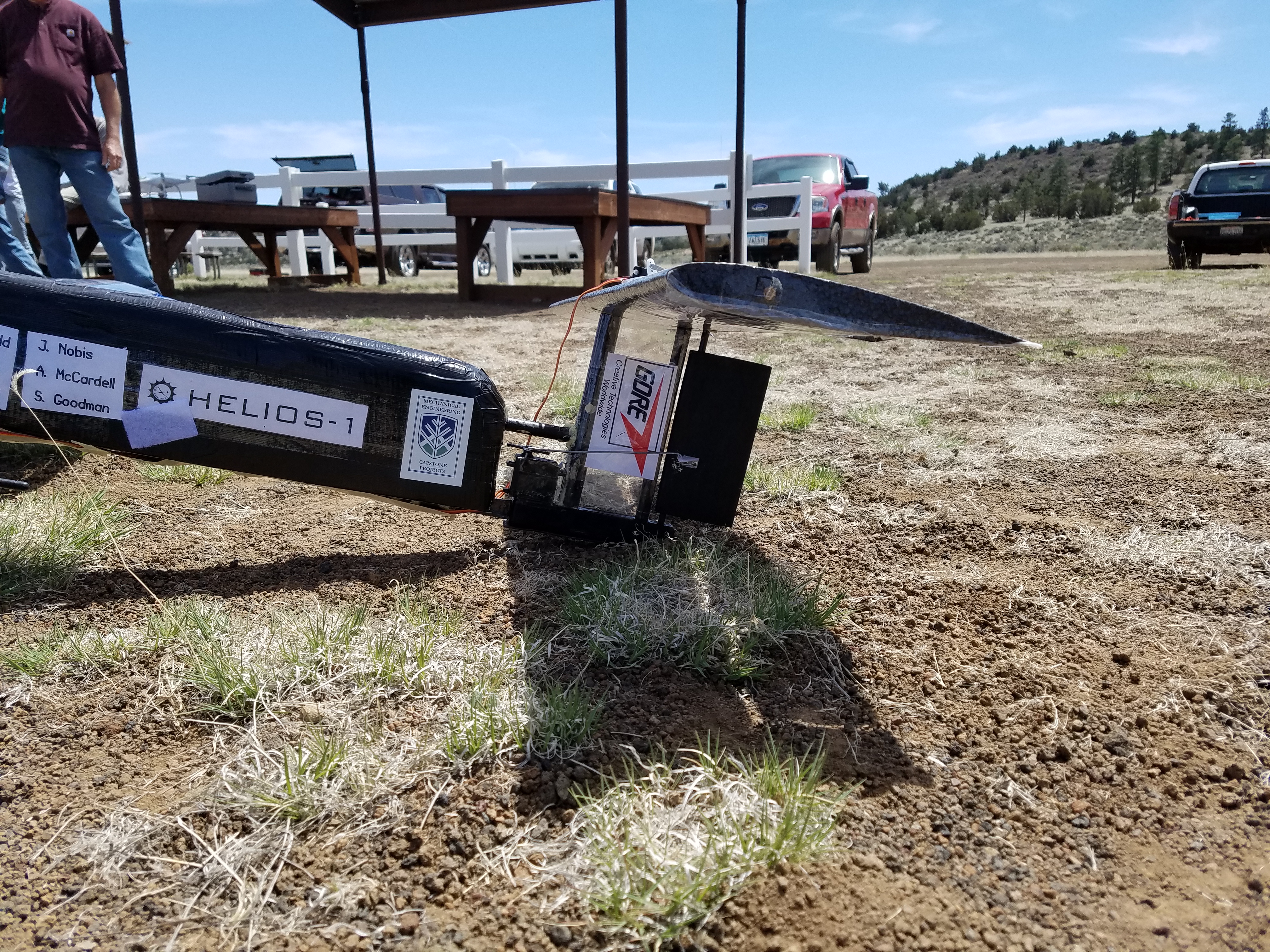
ULSA Current Design - HELIOS
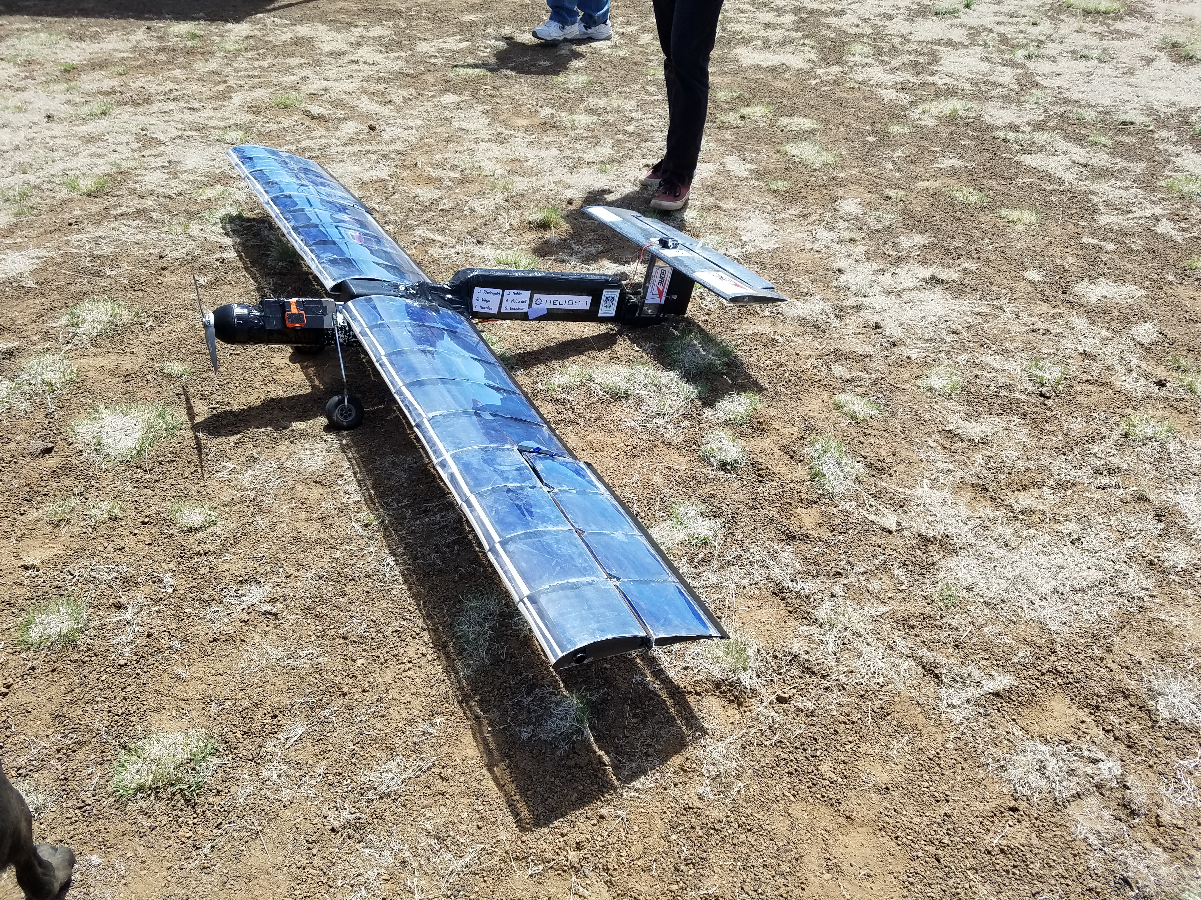
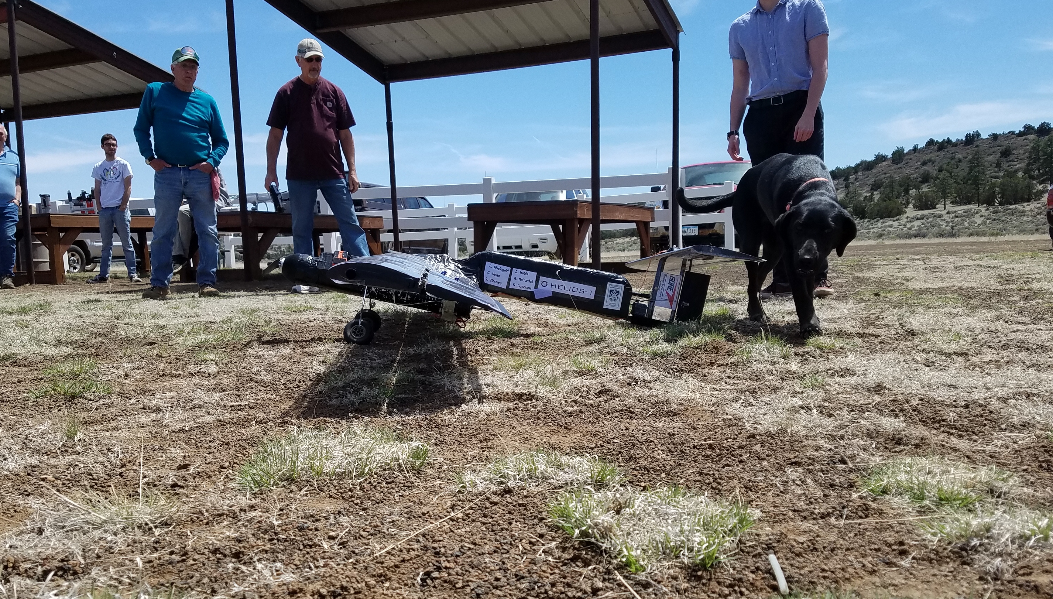
Two flight tests were conducted after completing the build, the first occurred on April 22nd, 2017 and the second was on April 26th 2017.
Full Aircraft Design
Lead: Joshua Nobis
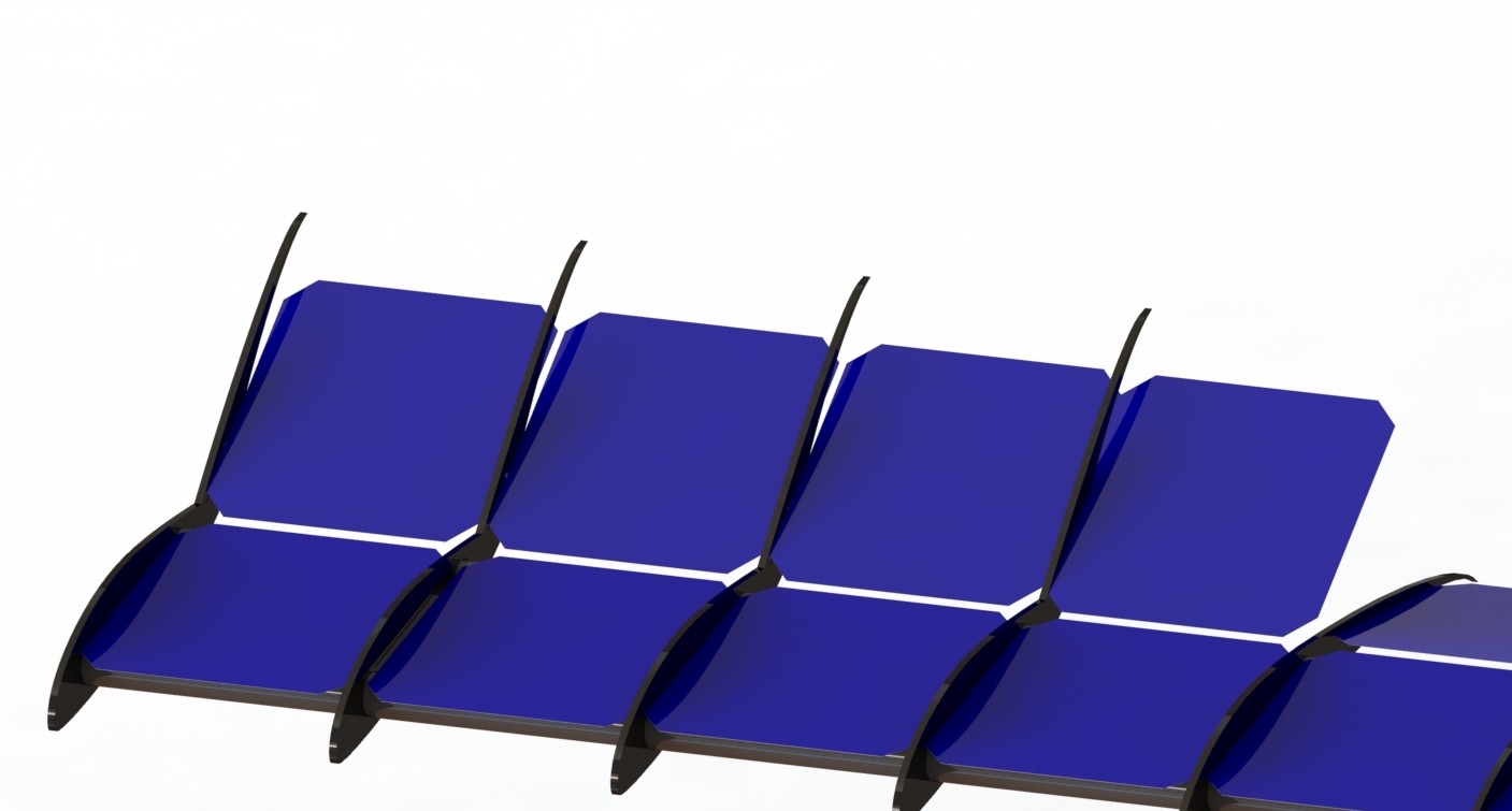
The updated ULSA design changed the fuselage design significantly, details of which can be found below. The full model design moved away from solid rods and instead uses hollowed tubes for the spars to reduce weight. In addition, the number of spars was brought down to only two. To compensate for the lack of space for the solar cells the size of the ribs was increased by 1.05x. Slots were added to the ribs to hold the solar cells, and the wooden paneling was removed. The ailerons were moved to the ends of the wings.
Many modifications were made to HELIOS after its maiden flight. The process was found to be very iterative as different situations posed various problems when trying to achieve a successful flight.
Wing Design
Lead: Jesse Rheingold
The S1223 airfoil was used at a 3° angle of attack that will provide double the lifting force required for the plane to take off. During the flight test, modifications to the dihedral increased the angle of attack significantly in an attempt to achieve greater lift.
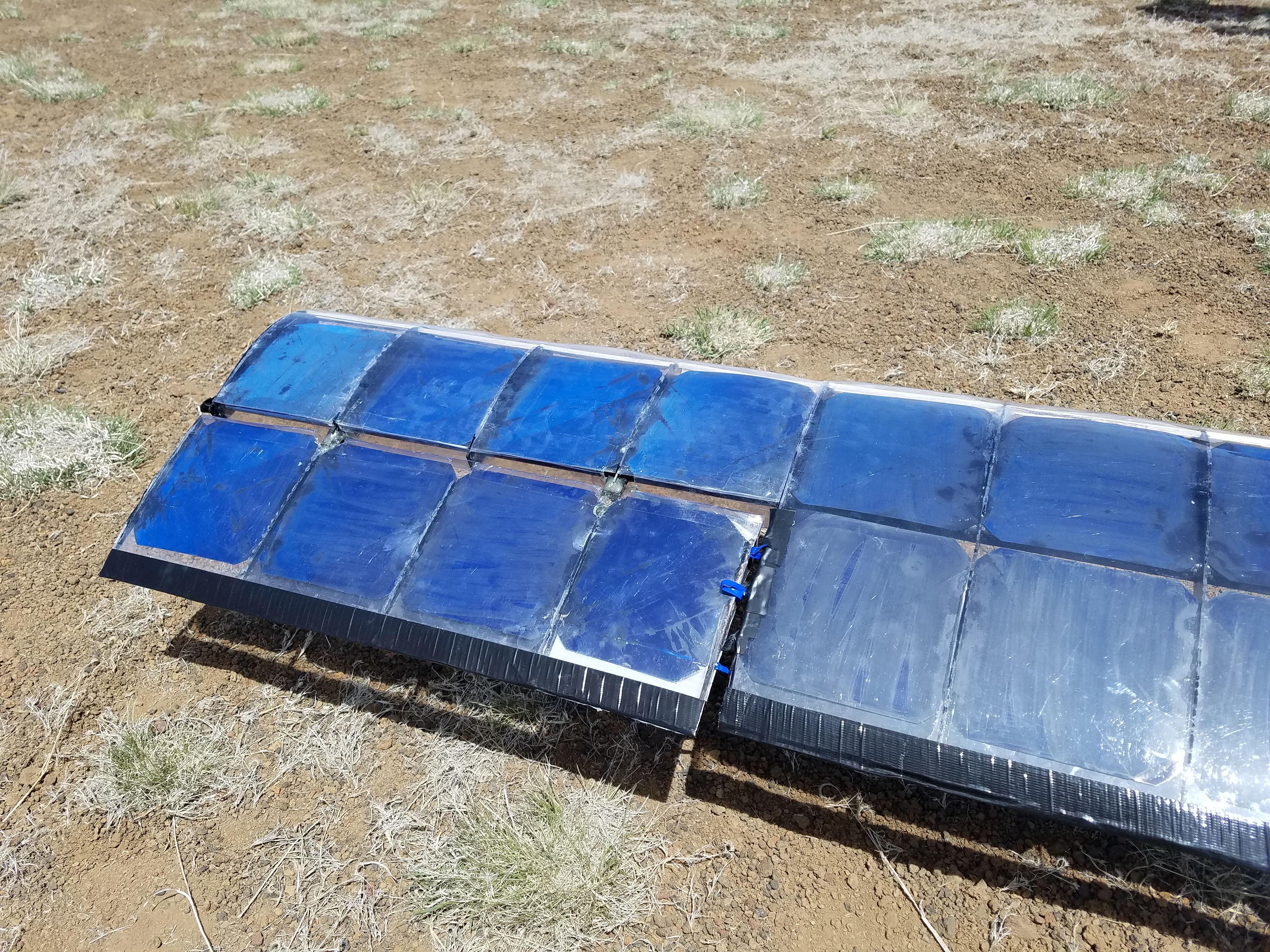
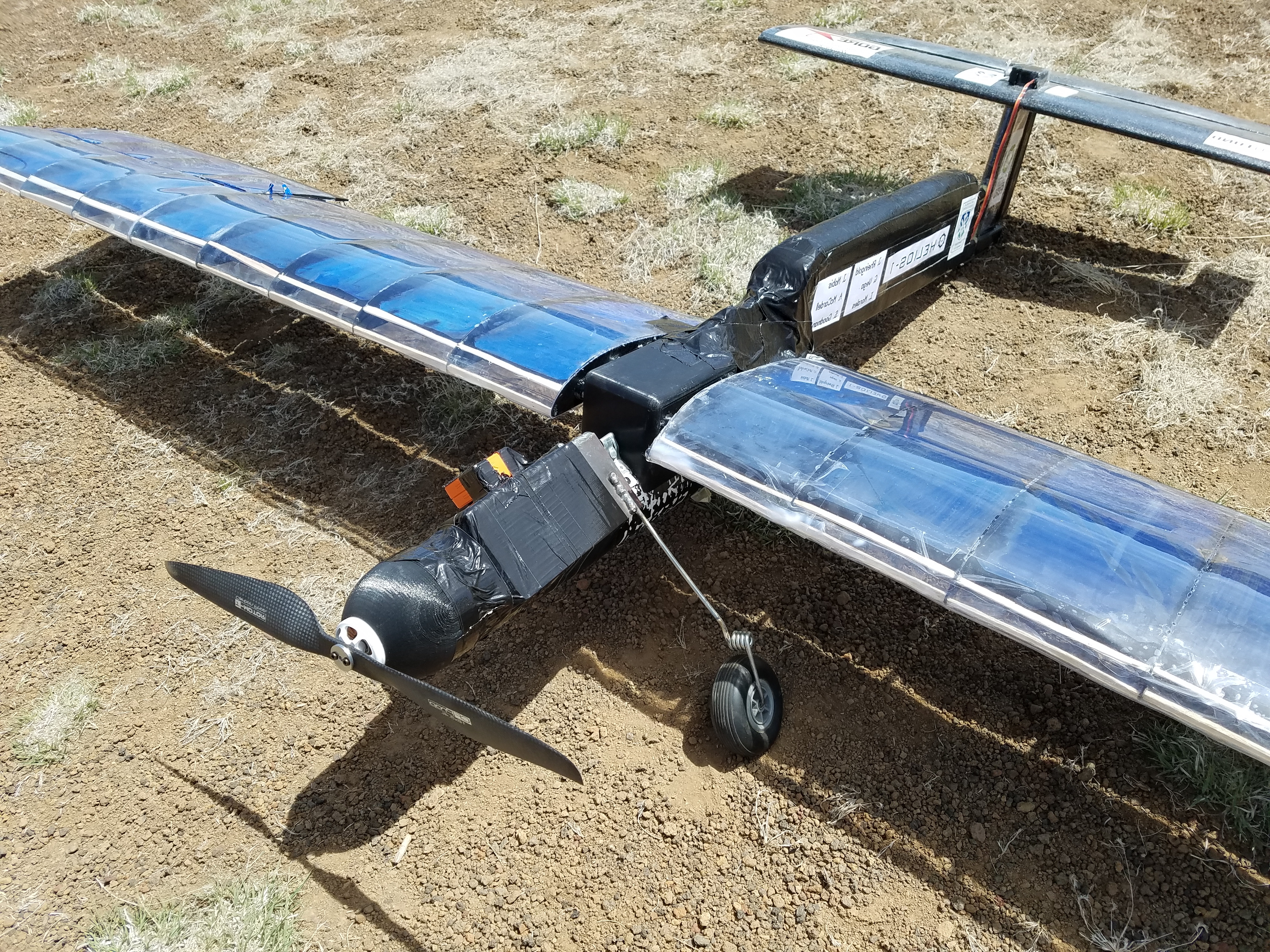
Due to insufficient technology available for the team to find optimal wing dimensions and a limited time frame to finalize a design by the end of the semester, the team was advised to facilitate acquiring wing platform dimensions based on what has been proved to work in the past. It was decided to make the airfoils out of carbon fiber, after balsa wood was found to be too brittle to endure a flight.
It was found later that that carbon fiber acted as a conducter with the non-insulated busbars connecting the solar cells, creating a dangerous live circuit when connected to the battery. It is suggested that for future projects that this issue be addressed with highest priority.
Aspect Ratio: 8.35
Wingspan: 8 ft
Chord Length: 12.5 in
Fuselage Design
Lead: Aria McCardell
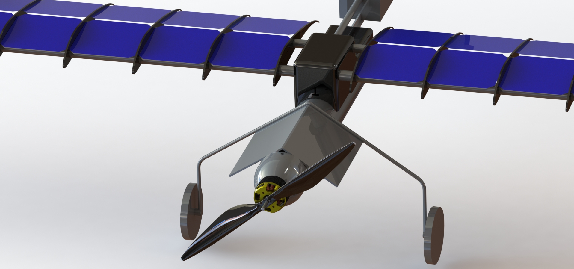
The fuselage was changed from a box design to a more aerodynamically sound cylindrical design. The cylinder is a thin-walled PVC piping that is large enough to hold the inner electronics safely. The motor is mounted to what will be a 3D printed nose cone. Two connectors will be used to attach the wings and tail boom.
After conducting center of gravity tests, HELIOS was found to be extremely tail heavy as the length of the tail boom created a significant moment arm. In response to this, the tail boom was shortened significantly and the fuselage was extended by about half a foot, to allow the battery to balance the aircraft.
Several 3D printed nose cones were used during flight tests as the material of the nose cone was found to undergo brittle failures after 2-3 flight attempts. Several propellors were also used as the flight crashed several times during the flight tests.
Avionics System
Lead: Ivan Morales
The avionics system was installed within the fuselage and included the first-person point of view camera and power generation system.
The electronics connect and powered the telemetry circuit board, the GPS unit, and the motor. The LiPo battery and 36 Solar Panels were connected in parallel with a Turnigy switch to open and close the circuit. This switch was controlled from the RC controller to remotely connect and disconnect the power coming from the solar panels. From this parallel power circuit, the electricity flows into a power module which funnels the power to the control board and into the electronic speed controller (ESC). The ESC takes the electrical inputs and converts the power into the appropriate speed for the motor.
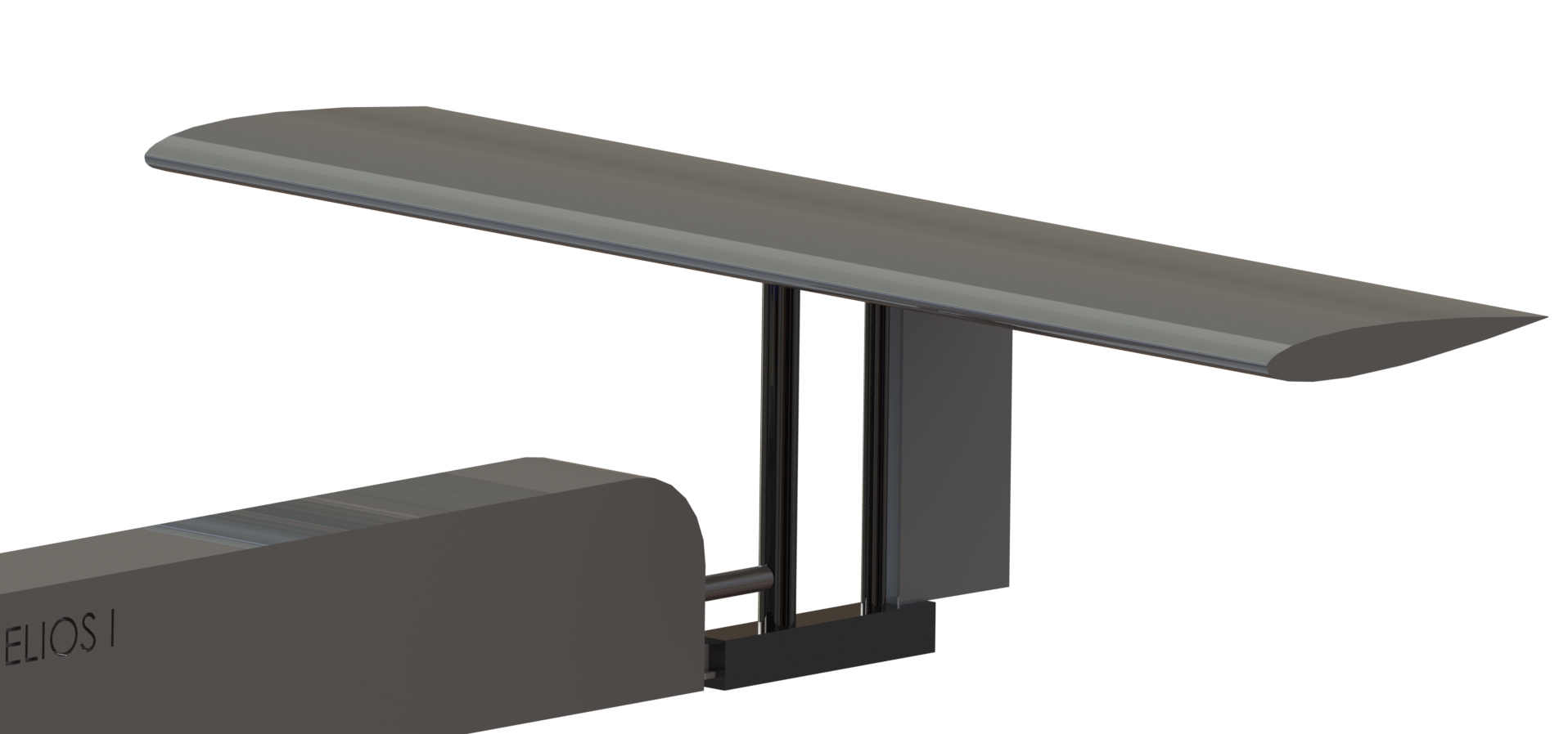
Tail Design
Lead: Gabriel Vega
The tail design was also changed in order to improve manufacturing processes and reduce lead times that are involved with laser cutting ribs. A T-tail configuration is still being used, however the elevator has been replaced with a symmetrical airfoil foam piece. A vertical rudder is being used paired with an elevator built into the foam airfoil. The vertical rudder was found to be too short of a control surface to be effective during take off.
The tail was connected to the fuselage using a carbon fiber T-shaped tail boom. The tail was found to undergo heavy torsion and thus a second tailboom was added to alleviate this. To connect the two tailbooms, a foam block was added as seen below.