Project Description
Problem Statement
Cobham Aerospace is in the process of designing a new radio to be used in different types of aircraft. This radio will be split into different modules, each doing a specific function. There is no existing test setup to analyze the communication between the modules of the radio when there is noise present. The problem proposed to our team is to develop the software for the communications between the different components of radio modules for Cobham Aerospace and then inject noise into the system. We must implement our software on a required field programmable gate array (FPGA), and interface with a graphical user interface (GUI). There will be Verilog software that will include methods for testing the communication link between different radio modules. The GUI will allow the user to monitor a communication uplink and test the communication under different noise conditions.
Description
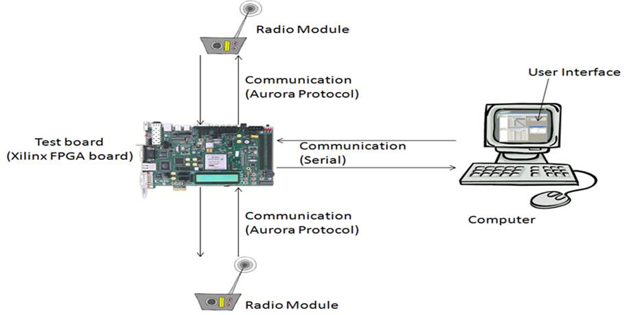
Our design centers around a software solution to the problem. The new radio under
development will be using Aurora protocol for communications between modules within the
radio. This protocol will allow for high-speed communications. The project proposed to our
team was to design a system to implement this protocol on an FPGA board to allow for testing.
The Xilinx Spartan 6 SP605 FPGA has been decided upon at this point in time.
The Verilog language will be written to implement the Aurora communication protocol on the board.
Once the protocol is established, noise or interference will be injected into the system through
hardware. The type of noise will be decided later into the project once the Verilog code to
implement the Aurora communication protocol on the FPGA is finished.
Once the Aurora communication protocol has been implemented and noise can be
injected into the system, the code will be added into the FPGA board to calculate the Bit Error
Rate (BER), and any other measurements requested. Finally, after the FPGA is able to
calculate BER, code will be added to allow the board to communicate with the computer via
USB, using RS232 communication protocol.
After the Verilog code for the FPGA is finished, a GUI will be programmed on a PC to
allow for ease of testing. The GUI will control the start and stop of the test, and will display the
results received from the FPGA. The GUI will be programmed in Visual Studios using C#.
Not many major design decisions have been made by our team, as many of the aspects
of the project have been decided by Cobham. As requested the code will be written in Verilog.
The one area that our group was able to make a decision was regarding how the GUI will be
developed. We looked at several options, such as using Java, Visual Basic, or Visual Studios.
To make the decision, we looked at the difficulty of programming in each language and then
also considered all of the team members' experience with the languages. Several team
members were experienced in Java and it is an easy language to program in, but it is difficult to
make GUIs in that language. Only one team member had ever worked with Visual Basic, with
no experience in constructing a GUI. However, a team member had experience in Visual
Studios producing GUIs. Also, we performed research online and found that Visual Studios is a
commonly used method to make GUIs. After considering all of the options, the team decided to
use Visual Studios to produce the GUI.
Diagram
Requirements and Specifications
Mechanical
Mechanically the software needs to be installed on a handheld module that can be used by one person. We want it to be mechanically easy to use as possible, and should be used in an ESD safe environment. The module is mechanically constrained to be connected with USB to other components and using RS232 communication protocol over serial to the personal computer. The GUI is also mechanically constrained by the need of having a touch interface.
| Interconnect | USB |
| Package | Must fit easily on a lab bench |
Electrical
Electrically we need to be able to interpret radio frequencies as accurately as possible for testing, and also be able to use our device with a wide range of different frequencies. We would like to keep the whole system as low power as possible, and would like it to interface completely using a GUI with no extra buttons for operation. We are electrically constrained to a particular FPGA board that we can use, and also a particular protocol.
| Internal Power (Xilinx Board) | 0.95-1.05 V |
| Communication Voltage (Xilinx Board) | 3.3 V |
| Interfacing (Xilinx board) | 1 Ethernet and 2 serial ports |
| Power Supply Power (Xilinx board) | 4.05 V (absolute max) |
Software
For software needs, our GUI will have text areas displaying the various Aurora protocol settings, and user buttons to manipulate the testing methods. We would like to minimize the number of buttons to only how many are needed so as to make the GUI as user friendly as possible while still having necessary testing requirement buttons. We are constrained by the need for certain values to be displayed and also certain buttons to be on the GUI.
| Values to be displayed on GUI | Aurora settings, bit error rate test results |
| Required buttons on GUI | Start, end, data file source, data transfer control options, options to repeatedly transfer data for prolonged BER testing |
| FPGA Programming Language | Verilog |
| GUI Programming Language | C# in Visual Studio development platform |
Environment
Environmentally we need our device to be robust enough to withstand frequent use. We would like it to be able to function in many different environmental conditions such as a variety of different temperatures and humidity, and to not be affected by mild vibrations. We are environmentally constrained only by the environment you would normally find in an average testing room at any manufacturing facility.
| Temperature of Environment | -65 to 150°C |
| Humidity | < 95% |
| Static Discharge | ESD safe environment (grounding straps and ESD mats) |
| Vibration | No specified limitations |
Documentation
For documentation we need to have our coded software commented, a user's guide for testing operations, an operator's manual for the GUI, and any manufacturer's documentation from components we used in the system. With the following, all document constraints for configuration, maintenance, and operation of the equipment are met.
| Operator's Manual for GUI | Yes |
| Maintenance Manual | No (See Xilinx maintenance manual) |
| User's Guide for Testing | Yes |
| Coding, GUI, and Verilog | Yes |
Proposal (Opens in a new tab)