Detailed Design
As detailed in the Pure Wave team's project proposal, using a shunt active power filter was determined to be the best approach to reducing harmonics in a system. The team did significant research on shunt active power filters and found that although many of these filters have been designed and analyzed, very few shunt active power filters have actually been built. Tradeoffs were made in order to ensure that the filter designed by the team was effective, easy to manufacture, and cost efficient.
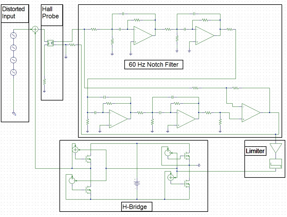
The team's detailed design was modeled and simulated using PSpice software. PSpice can be downloaded for free here, and the team's detailed design file is available here (right-click the link and click 'save link as'). To look at an image of the design schematic, where key parts of the design have been labeled, click here. As can be seen in the labeled design, there are 4 important components required for the team's design (the distorted input is created by the non-linear load and is included for simulation purposes only). These important components are listed and briefly described below.
Hall Probe
Hall probes are devices which use electromagnetic phenomena to measure the current flowing through a line. That is, the output of a Hall probe is a voltage signal which is a scaled down duplicate the current signal found on a line. The Pure Wave team's design uses a Hall probe to measure the distorted current signal which is caused by a non-linear load. The Hall probe's output is then passed through a 60 Hz Notch Filter.
60 Hz Notch Filter
A filter is used to separate the desireable and the undesireable. A 60 Hz notch filter is used to remove the 60 Hz component of a signal without affecting other signal components (e.g. the 180, 300, and 420 Hz signals are unaffected by a good 60 Hz notch filter). Designing a 60 Hz notch filter was difficult, and so a free program created by Texas Instruments (available here) was used by the team. By inputting filter specifications into this easy to use program, a hardware design and filter characteristics are produced. After testing several different sets of specifications, a finalized 60 Hz notch filter was created. The output of this filter is then fed into a limiter.
Limiter
Limiters are devices which amplify voltage signals until a voltage limit is reached. That is, if a low voltage signal is fed into a limiter, the voltage signal is amplified until the limiter bounds are reached. Thus, if a limiter with 10 V bounds is used then a .1 V input will result in a 10 V output, and a -.1 V input will result in a -10 V output. In this way, a sinusodial wave can be converted into a square wave. The sqare wave output of the limiter is used to control the H-brige.
H-Bridge
By controlling when transistor pairs conduct, the H-bridge used in the Pure Wave team's design is used to inject or remove current from a system. H-bridge designs are extremely complicated, and so a simplified version was used for simulation purposes.
After the team's detailed design was finalized, the next step was to begin building and testing.